
Concrete Masonry: Navigating Energy Codes to Maximize Thermal Mass Performance

This course examines how concrete masonry’s thermal mass contributes to energy efficiency across a range of climate zones and building types. It describes the role of heat capacity and mass wall behavior in overall thermal performance and outlines how these attributes are addressed within current energy codes. The session reviews prescriptive, trade-off, and whole-building performance pathways in ASHRAE 90.1 and the IECC, highlighting how CMU assemblies are evaluated in each method. The course also presents commonly used compliance tools, and shows how they support energy-code documentation for mass-wall designs.
What Non-Engineers Need to Know About Concrete Masonry

This course provides a foundational understanding of structural concrete masonry for professionals outside the field of structural engineering. It explores key aspects of concrete masonry systems, including block types, mortar and grout properties, reinforcement strategies, and design practices. Participants will gain insights into how structural masonry is applied in modern construction, its advantages over alternative systems, and the common design errors to avoid. Learners will understand the cost, time, and sustainability benefits of choosing efficient masonry solutions in building design.
Partition Wall Calculator
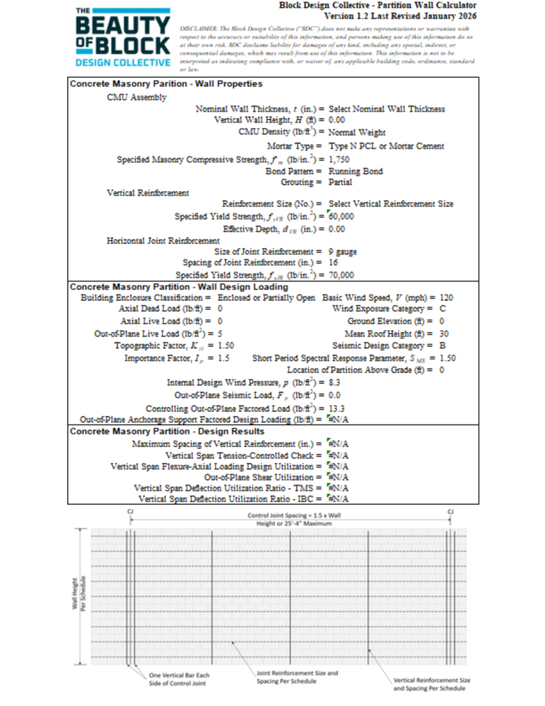
This calculator designs interior concrete masonry partition walls in accordance with the strength design provisions of TMS 402/602-22 and the loading criteria of ASCE/SEI 7-22. Highlighted cells are user inputs. Inputs and outputs use inch-pound units.
Architectural CMU Basics

Most people know what a concrete block is, but beyond the standard units used in basements or concealed structural applications, architectural concrete masonry units (CMU) are made to be seen and celebrated. Architectural block provides a diverse selection of bond patterns, colors and finishes — delivering versatility that supports performance requirements and design intent. This block bite reviews the array of aesthetic possibilities available when using architectural concrete masonry.
Concrete Masonry Elevator and Stairwell Building Core Design Guide
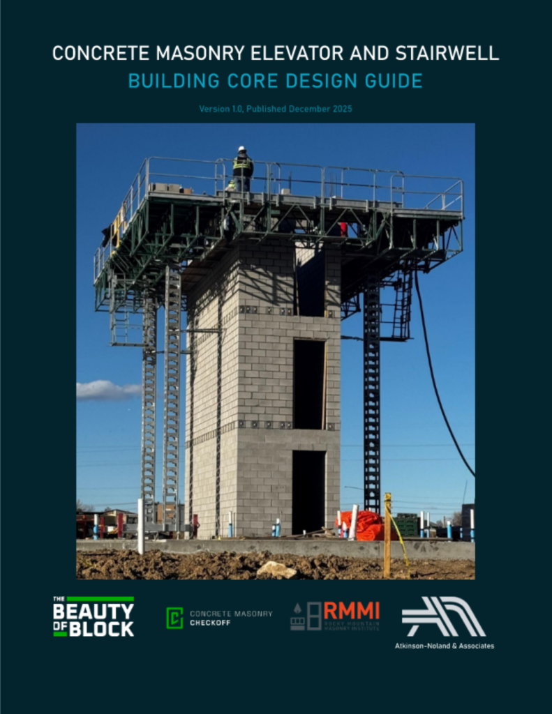
Elevator and stairwell building cores are often used to provide structural stability to buildings and to transfer load from upper stories to the foundations. Such building cores are often constructed using reinforced concrete masonry. Concrete masonry construction is ideal in this function as it is durable, has a high fire resistance, excellent sound resistance, rapid construction, and is easily reinforceable.
Designer Checklist for Unreinforced Loadbearing Concrete Masonry Walls Based on TMS 402/602-22
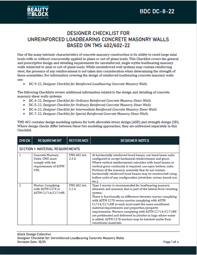
One of the many intrinsic characteristics of concrete masonry construction is its ability to resist large axial loads with or without concurrently applied in-plane or out-of-plane loads. This Checklist covers the general and prescriptive design and detailing requirements for unreinforced, single wythe loadbearing masonry walls subjected to axial or out-of-plane loads. While unreinforced wall systems may contain reinforcing steel, the presence of any reinforcement is not taken into consideration when determining the strength of these assemblies. For information covering the design of reinforced loadbearing concrete masonry walls see:
•
DC-9-22, Designer Checklist for Reinforced Loadbearing Concrete Masonry Walls
The following Checklists review additional information related to the design and detailing of concrete masonry shear walls systems:
•
DC-4-22, Designer Checklist for Ordinary Reinforced Concrete Masonry Shear Walls
•
DC-5-22, Designer Checklist for Ordinary Reinforced Concrete Masonry Shear Walls
•
DC-6-22, Designer Checklist for Intermediate Reinforced Concrete Masonry Shear Walls
•
DC-7-22, Designer Checklist for Special Reinforced Concrete Masonry Shear Walls
TMS 402 contains design modeling options for both allowable stress design (ASD) and strength design (SD). Where design checks differ between these two modeling approaches, they are addressed separately in this Checklist.
CHECK REQUIREMENT REFERENCE DESIGNER NOTE
Designer Checklist for Ordinary Plain and Detailed Plain Unreinforced Shear Concrete Masonry Shear Walls Based on TMS 402/602-22
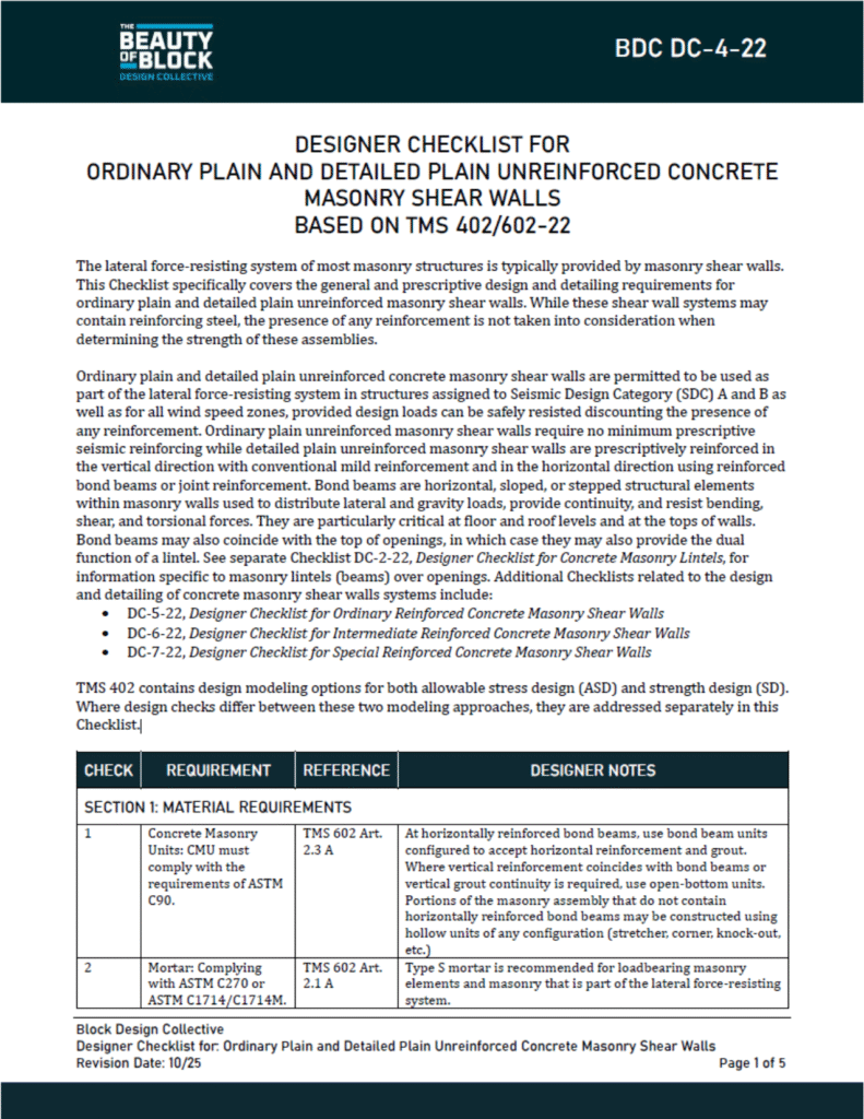
The lateral force-resisting system of most masonry structures is typically provided by masonry shear walls. This Checklist specifically covers the general and prescriptive design and detailing requirements for ordinary plain and detailed plain unreinforced masonry shear walls. While these shear wall systems may contain reinforcing steel, the presence of any reinforcement is not taken into consideration when determining the strength of these assemblies.
Ordinary plain and detailed plain unreinforced concrete masonry shear walls are permitted to be used as part of the lateral force-resisting system in structures assigned to Seismic Design Category (SDC) A and B as well as for all wind speed zones, provided design loads can be safely resisted discounting the presence of any reinforcement. Ordinary plain unreinforced masonry shear walls require no minimum prescriptive seismic reinforcing while detailed plain unreinforced masonry shear walls are prescriptively reinforced in the vertical direction with conventional mild reinforcement and in the horizontal direction using reinforced bond beams or joint reinforcement. Bond beams are horizontal, sloped, or stepped structural elements within masonry walls used to distribute lateral and gravity loads, provide continuity, and resist bending, shear, and torsional forces. They are particularly critical at floor and roof levels and at the tops of walls. Bond beams may also coincide with the top of openings, in which case they may also provide the dual function of a lintel. See separate Checklist DC-2-22, Designer Checklist for Concrete Masonry Lintels, for information specific to masonry lintels (beams) over openings. Additional Checklists related to the design and detailing of concrete masonry shear walls systems include:
•
DC-5-22, Designer Checklist for Ordinary Reinforced Concrete Masonry Shear Walls
•
DC-6-22, Designer Checklist for Intermediate Reinforced Concrete Masonry Shear Walls
•
DC-7-22, Designer Checklist for Special Reinforced Concrete Masonry Shear Walls
TMS 402 contains design modeling options for both allowable stress design (ASD) and strength design (SD). Where design checks differ between these two modeling approaches, they are addressed separately in this Checklist.
Designer Checklist for Special Reinforced Concrete Masonry Shear Walls Based on TMS 402/602-22

The lateral force-resisting system of most masonry structures is typically provided by masonry shear walls. This Checklist specifically covers the general and prescriptive design and detailing requirements for special reinforced masonry shear walls. Special reinforced concrete masonry shear walls are permitted to be used as part of the lateral force-resisting system in structures assigned to any Seismic Design Category (SDC) as well as for all wind speed zones. Special reinforced masonry shear walls are reinforced in the vertical direction with conventional mild reinforcement and in the horizontal direction typically using reinforced bond beams. Bond beams are horizontal, sloped, or stepped structural elements within masonry walls used
to distribute lateral and gravity loads, provide continuity, and resist bending, shear, and torsional forces. They are particularly critical at floor and roof levels and at the tops of walls. Bond beams may also coincide with the top of openings, in which case they may also provide the dual function of a lintel. See separate Checklist DC-2-22, Designer Checklist for Concrete Masonry Lintels, for information specific to masonry lintels (beams) over openings. Additional Checklists related to the design and detailing of concrete masonry shear walls systems include:
• DC-4-22, Designer Checklist for Detailed Plain Concrete Masonry Shear Walls
• DC-5-22, Designer Checklist for Special Reinforced Concrete Masonry Shear Walls
• DC-6-22, Designer Checklist for Intermediate Reinforced Concrete Masonry Shear Walls
TMS 402 contains design modeling options for both allowable stress design (ASD) and strength design (SD). Where design checks differ between these two modeling approaches, they are addressed separately in this Checklist.
Designer Checklist for Intermediate Reinforced Concrete Masonry Shear Walls Based on TMS 402/602-22

The lateral force-resisting system of most masonry structures is typically provided by masonry shear walls. This Checklist specifically covers the general and prescriptive design and detailing requirements for intermediate reinforced masonry shear walls. Intermediate reinforced concrete masonry shear walls are permitted to be used as part of the lateral force-resisting system in structures assigned to Seismic Design Category (SDC) A, B, and C as well as for all wind speed zones. Intermediate reinforced masonry shear walls are reinforced in the vertical direction with conventional mild reinforcement and in the horizontal direction using reinforced bond beams or joint reinforcement. Bond beams are horizontal, sloped, or stepped structural elements within masonry walls used to distribute lateral and gravity loads, provide continuity, and resist bending, shear, and torsional forces. They are particularly critical at floor and roof levels and at the tops of walls. Bond beams may also coincide with the top of openings, in which case they may also provide the dual function of a lintel. See separate Checklist DC-2-22, Designer Checklist for Concrete Masonry Lintels, for information specific to masonry lintels (beams) over openings. Additional Checklists related to the design and detailing of concrete masonry shear walls systems include:
• DC-4-22, Designer Checklist for Detailed Plain Concrete Masonry Shear Walls
• DC-5-22, Designer Checklist for Ordinary Reinforced Concrete Masonry Shear Walls
• DC-7-22, Designer Checklist for Special Reinforced Concrete Masonry Shear Walls
TMS 402 contains design modeling options for both allowable stress design (ASD) and strength design (SD). Where design checks differ between these two modeling approaches, they are addressed separately in this Checklist.
Designer Checklist for Ordinary Reinforced Concrete Masonry Shear Walls Based on TMS 402/602-22
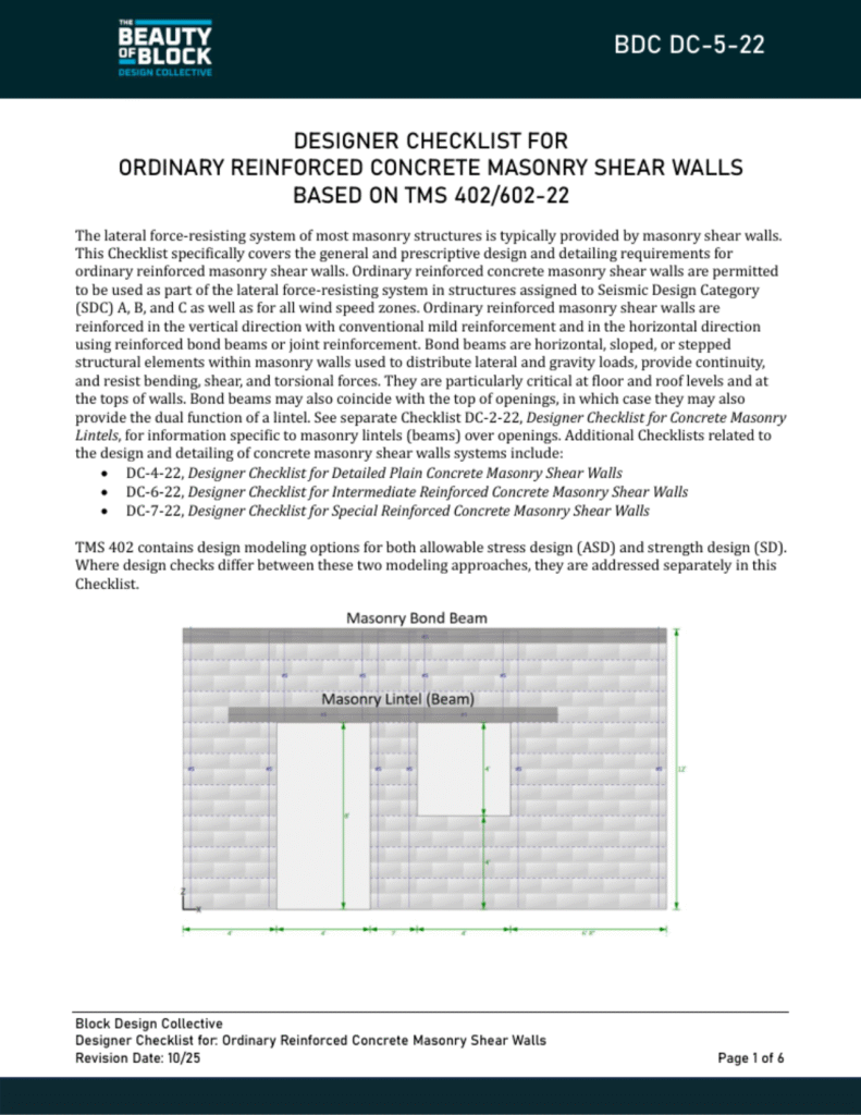
The lateral force-resisting system of most masonry structures is typically provided by masonry shear walls. This Checklist specifically covers the general and prescriptive design and detailing requirements for ordinary reinforced masonry shear walls. Ordinary reinforced concrete masonry shear walls are permitted to be used as part of the lateral force-resisting system in structures assigned to Seismic Design Category
(SDC) A, B, and C as well as for all wind speed zones. Ordinary reinforced masonry shear walls are reinforced in the vertical direction with conventional mild reinforcement and in the horizontal direction using reinforced bond beams or joint reinforcement. Bond beams are horizontal, sloped, or stepped structural elements within masonry walls used to distribute lateral and gravity loads, provide continuity, and resist bending, shear, and torsional forces. They are particularly critical at floor and roof levels and at
the tops of walls. Bond beams may also coincide with the top of openings, in which case they may also provide the dual function of a lintel. See separate Checklist DC-2-22, Designer Checklist for Concrete Masonry Lintels, for information specific to masonry lintels (beams) over openings. Additional Checklists related to
the design and detailing of concrete masonry shear walls systems include:
• DC-4-22, Designer Checklist for Detailed Plain Concrete Masonry Shear Walls
• DC-6-22, Designer Checklist for Intermediate Reinforced Concrete Masonry Shear Walls
• DC-7-22, Designer Checklist for Special Reinforced Concrete Masonry Shear Walls
TMS 402 contains design modeling options for both allowable stress design (ASD) and strength design (SD).
Where design checks differ between these two modeling approaches, they are addressed separately in this Checklist.