
Designer Checklist for Special Reinforced Concrete Masonry Shear Walls Based on TMS 402/602-22

The lateral force-resisting system of most masonry structures is typically provided by masonry shear walls. This Checklist specifically covers the general and prescriptive design and detailing requirements for special reinforced masonry shear walls. Special reinforced concrete masonry shear walls are permitted to be used as part of the lateral force-resisting system in structures assigned to any Seismic Design Category (SDC) as well as for all wind speed zones. Special reinforced masonry shear walls are reinforced in the vertical direction with conventional mild reinforcement and in the horizontal direction typically using reinforced bond beams. Bond beams are horizontal, sloped, or stepped structural elements within masonry walls used
to distribute lateral and gravity loads, provide continuity, and resist bending, shear, and torsional forces. They are particularly critical at floor and roof levels and at the tops of walls. Bond beams may also coincide with the top of openings, in which case they may also provide the dual function of a lintel. See separate Checklist DC-2-22, Designer Checklist for Concrete Masonry Lintels, for information specific to masonry lintels (beams) over openings. Additional Checklists related to the design and detailing of concrete masonry shear walls systems include:
• DC-4-22, Designer Checklist for Detailed Plain Concrete Masonry Shear Walls
• DC-5-22, Designer Checklist for Special Reinforced Concrete Masonry Shear Walls
• DC-6-22, Designer Checklist for Intermediate Reinforced Concrete Masonry Shear Walls
TMS 402 contains design modeling options for both allowable stress design (ASD) and strength design (SD). Where design checks differ between these two modeling approaches, they are addressed separately in this Checklist.
Designer Checklist for Intermediate Reinforced Concrete Masonry Shear Walls Based on TMS 402/602-22

The lateral force-resisting system of most masonry structures is typically provided by masonry shear walls. This Checklist specifically covers the general and prescriptive design and detailing requirements for intermediate reinforced masonry shear walls. Intermediate reinforced concrete masonry shear walls are permitted to be used as part of the lateral force-resisting system in structures assigned to Seismic Design Category (SDC) A, B, and C as well as for all wind speed zones. Intermediate reinforced masonry shear walls are reinforced in the vertical direction with conventional mild reinforcement and in the horizontal direction using reinforced bond beams or joint reinforcement. Bond beams are horizontal, sloped, or stepped structural elements within masonry walls used to distribute lateral and gravity loads, provide continuity, and resist bending, shear, and torsional forces. They are particularly critical at floor and roof levels and at the tops of walls. Bond beams may also coincide with the top of openings, in which case they may also provide the dual function of a lintel. See separate Checklist DC-2-22, Designer Checklist for Concrete Masonry Lintels, for information specific to masonry lintels (beams) over openings. Additional Checklists related to the design and detailing of concrete masonry shear walls systems include:
• DC-4-22, Designer Checklist for Detailed Plain Concrete Masonry Shear Walls
• DC-5-22, Designer Checklist for Ordinary Reinforced Concrete Masonry Shear Walls
• DC-7-22, Designer Checklist for Special Reinforced Concrete Masonry Shear Walls
TMS 402 contains design modeling options for both allowable stress design (ASD) and strength design (SD). Where design checks differ between these two modeling approaches, they are addressed separately in this Checklist.
Designer Checklist for Ordinary Reinforced Concrete Masonry Shear Walls Based on TMS 402/602-22
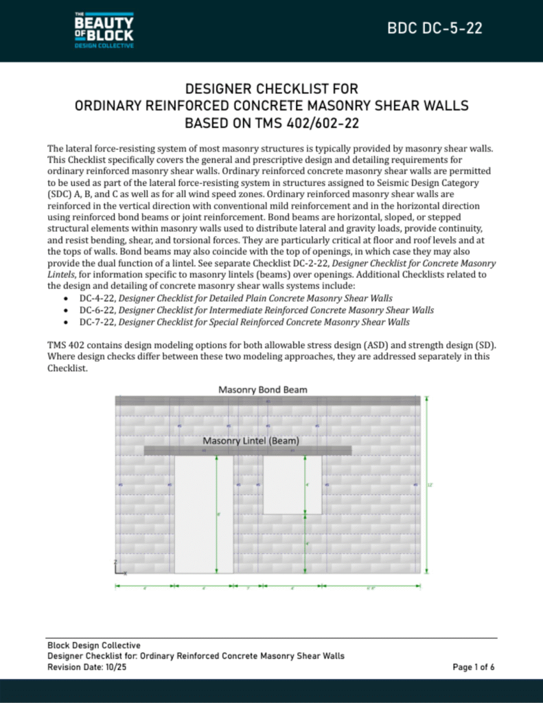
The lateral force-resisting system of most masonry structures is typically provided by masonry shear walls. This Checklist specifically covers the general and prescriptive design and detailing requirements for ordinary reinforced masonry shear walls. Ordinary reinforced concrete masonry shear walls are permitted to be used as part of the lateral force-resisting system in structures assigned to Seismic Design Category
(SDC) A, B, and C as well as for all wind speed zones. Ordinary reinforced masonry shear walls are reinforced in the vertical direction with conventional mild reinforcement and in the horizontal direction using reinforced bond beams or joint reinforcement. Bond beams are horizontal, sloped, or stepped structural elements within masonry walls used to distribute lateral and gravity loads, provide continuity, and resist bending, shear, and torsional forces. They are particularly critical at floor and roof levels and at
the tops of walls. Bond beams may also coincide with the top of openings, in which case they may also provide the dual function of a lintel. See separate Checklist DC-2-22, Designer Checklist for Concrete Masonry Lintels, for information specific to masonry lintels (beams) over openings. Additional Checklists related to
the design and detailing of concrete masonry shear walls systems include:
• DC-4-22, Designer Checklist for Detailed Plain Concrete Masonry Shear Walls
• DC-6-22, Designer Checklist for Intermediate Reinforced Concrete Masonry Shear Walls
• DC-7-22, Designer Checklist for Special Reinforced Concrete Masonry Shear Walls
TMS 402 contains design modeling options for both allowable stress design (ASD) and strength design (SD).
Where design checks differ between these two modeling approaches, they are addressed separately in this Checklist.
Concrete Masonry: From Manufacturing to Structural Applications

This module explores the fundamentals of concrete masonry construction, beginning with the manufacturing process of concrete masonry units (CMUs) and examining both standard gray block and architectural finishes.
Participants will learn about various CMU shapes, sizes, and modular design principles that optimize construction efficiency. The course covers essential structural considerations, including the differences between unit compressive strength and specified masonry assembly strength (f’m), and examines how tall structures can be built using concrete masonry.
Additionally, the module introduces efficient design strategies that help reduce both project costs and embodied carbon, making concrete masonry an economical and sustainable building solution.
Designer Checklist for Anchorage into Concrete Masonry Based on TMS 402/602-22
Anchor bolts are used to connect masonry to other elements within a structure for support and load transfer. TMS 402/602 addresses the design and installation of anchors embedded in freshly placed grout, however, post-installed anchors are commonly used as well. Given the proprietary nature of most post-installed anchor bolts, they are outside of the scope of this Checklist. The design of veneer anchorage (e.g., veneer ties) is also outside the scope of this Checklist.
TMS 402/602 addresses two types of embedded anchors: bent-bar anchors and headed anchors. Both are addressed in this Checklist.
This Checklist is applicable to anchors embedded in masonry construction designed in accordance with TMS 402/602 for commercial structures covered under the International Building Code. Single family residential construction covered under the International Residential Code has different design, detailing, and construction requirements specific an anchor bolts embedded in masonry.
TMS 402 contains design modeling options for both allowable stress design (ASD) and strength design (SD). Where design checks differ between these two modeling approaches, they are addressed separately in this Checklist.
Designer Checklist for Concrete Masonry Lintels Based on TMS 402/602-22
Concrete masonry lintels (the term beam is used interchangeably with lintel) are horizontal elements spanning openings in masonry walls (doors, windows, etc.). They are required to safely transfer loads from above to the wall areas adjacent to the opening. Lintels are subject to combined flexural and shear stresses and must be detailed to control cracking, deflection, and ensure durability. See separate Checklist DC-3-22, Designer Checklist for Concrete Masonry Bond Beams, for design and detailing requirements for masonry beams built into the field of the masonry assembly.
TMS 402 contains design modeling options for both allowable stress design (ASD) and strength design (SD). Where design checks differ between these two modeling approaches, they are addressed separately in this Checklist.
Masonry Compressive Strength Calculator
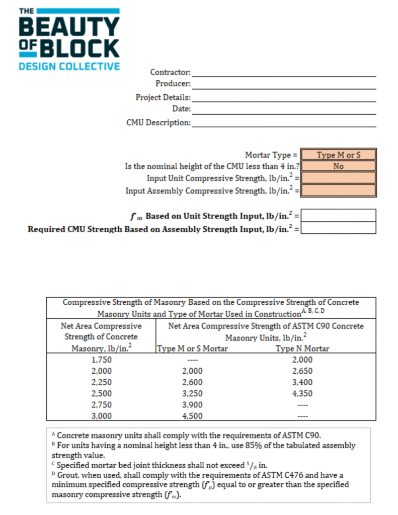
This calculator uses the unit strength table of TMS 602 (shown below) to determine the unit compressive strength required to achieve a user-specified masonry assembly compressive strength (f’m) – or determines the resulting assembly compressive strength (f’m) based on the user defined unit compressive strength. This calculator can be used with either the 2016 or 2022 editions of TMS 402/602.
Section Properties and Wall Weights Calculator
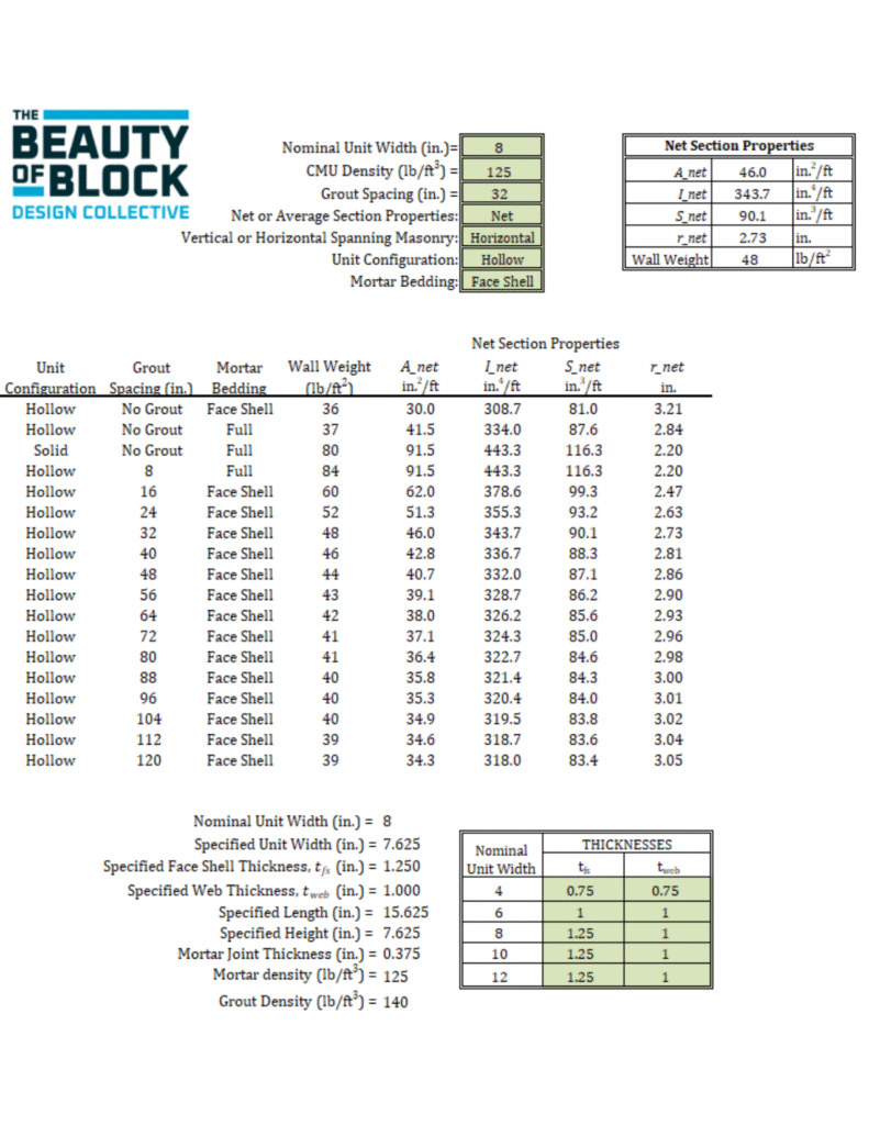
This calculator determines net and average cross-sectional properties based on user defined inputs. Net section properties represent the smallest cross-section of an assembly and are used for calculating assembly strength. Average section properties represent the average cross-section of an assembly and are used for calculating assembly stiffness. This calculator determines the net cross-sectional properties through a plane concurrent with a mortar joint while average section properties are determined through a plane concurrent with the mid-height or mid-length of a unit in the assembly.
Lap Splice & Development Length Calculator
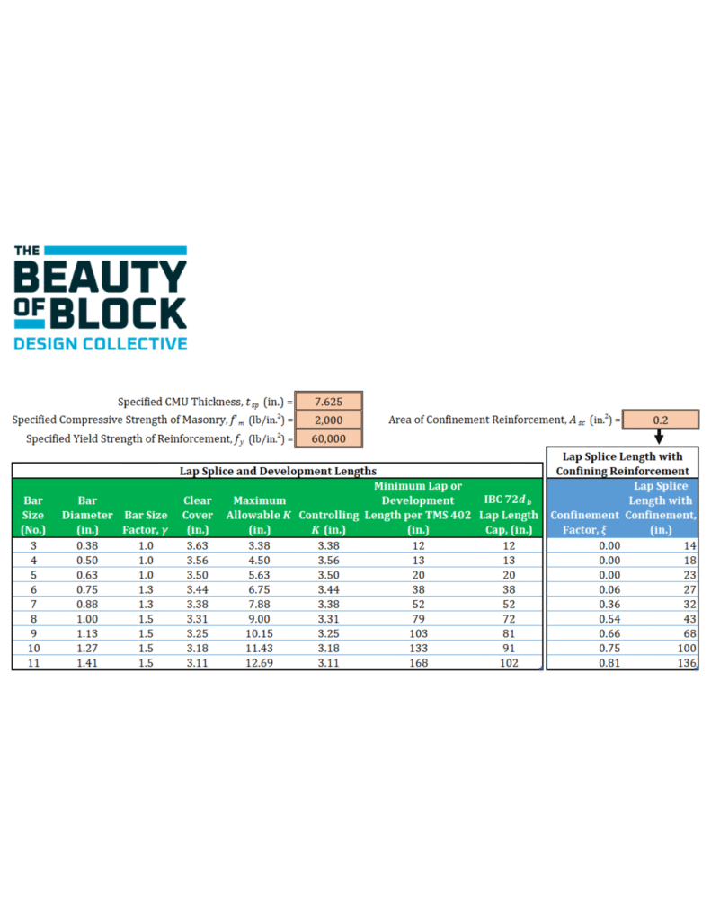
This calculator is based on the provisions of TMS 402/602-16 and TMS 402/602-22, Building Code Requirements and Specification for Masonry Structures. As there is no functional difference between the requirements of these two editions of the masonry design standard pertaining to the determination of minimum lap and development lengths, either edition is applicable.
Designer Checklist for Concrete Masonry Partitions Based on TMS 402/602-22

Concrete masonry partition walls are interior walls without structural function commonly used for space separation, fire resistance, and sound insulation. While partitions do not carry vertical loads other than their own weight, they are subject to lateral loading due to HVAC pressurization, occupants, seismic loads, and internal pressures from external wind entering into the structure through openings or small leakage paths. This checklist is applicable to concrete masonry partitions based on TMS 402/602-22.
TMS 402 contains design modeling options for both allowable stress design (ASD) and strength design (SD). Where design checks differ between these two modeling approaches, they are addressed separately in this Checklist.