The lateral force-resisting system of most masonry structures is typically provided by masonry shear walls. This Checklist specifically covers the general and prescriptive design and detailing requirements for ordinary plain and detailed plain unreinforced masonry shear walls. While these shear wall systems may contain reinforcing steel, the presence of any reinforcement is not taken into consideration when determining the strength of these assemblies.
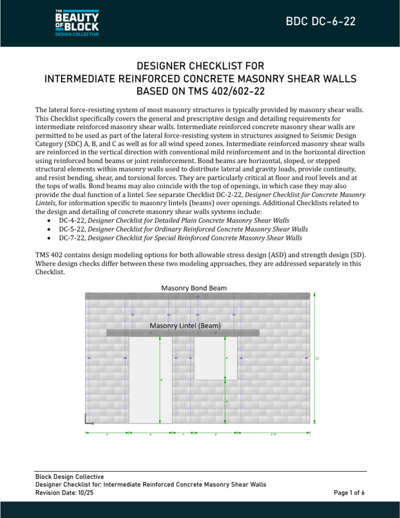
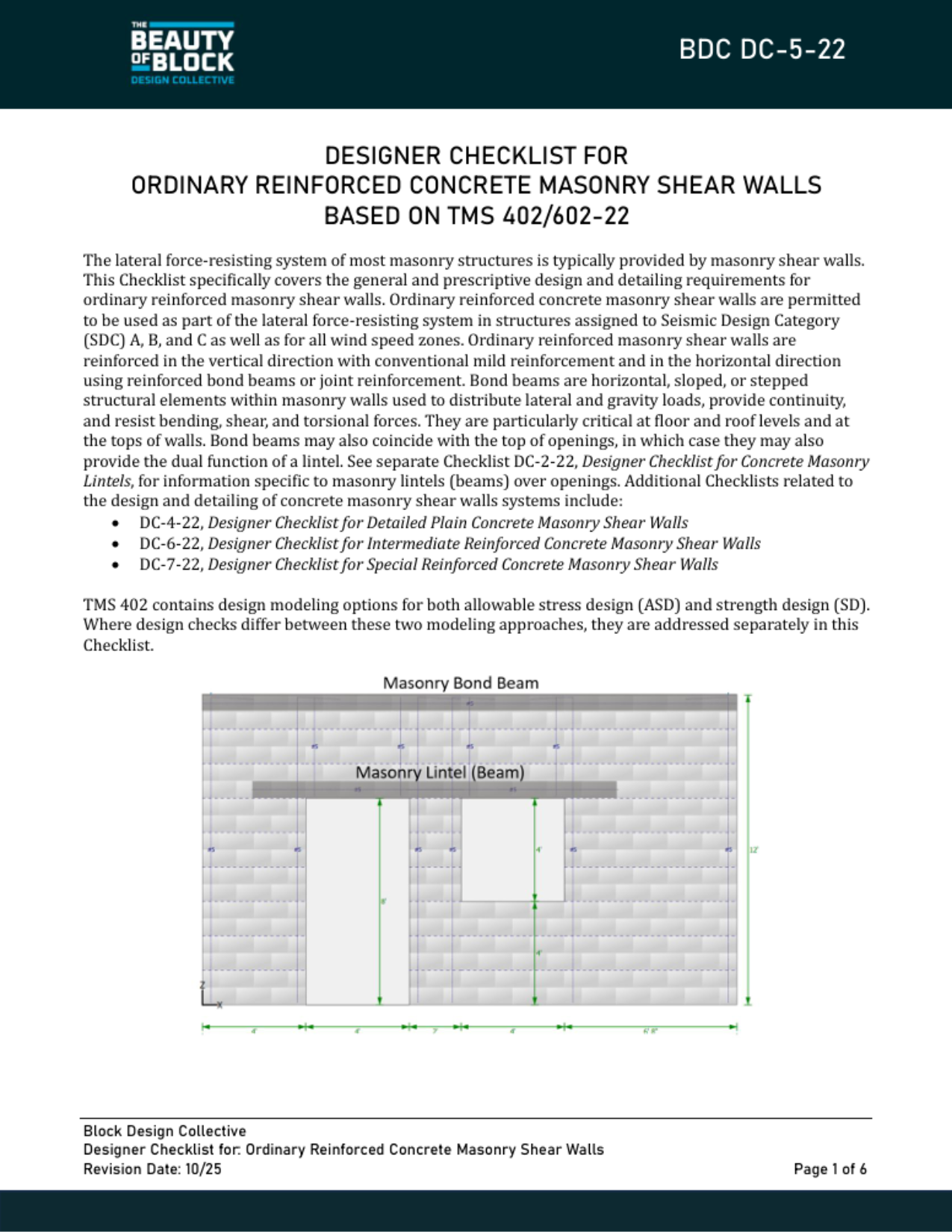
Ordinary plain and detailed plain unreinforced concrete masonry shear walls are permitted to be used as part of the lateral force-resisting system in structures assigned to Seismic Design Category (SDC) A and B as well as for all wind speed zones, provided design loads can be safely resisted discounting the presence of any reinforcement. Ordinary plain unreinforced masonry shear walls require no minimum prescriptive seismic reinforcing while detailed plain unreinforced masonry shear walls are prescriptively reinforced in the vertical direction with conventional mild reinforcement and in the horizontal direction using reinforced bond beams or joint reinforcement. Bond beams are horizontal, sloped, or stepped structural elements within masonry walls used to distribute lateral and gravity loads, provide continuity, and resist bending, shear, and torsional forces. They are particularly critical at floor and roof levels and at the tops of walls. Bond beams may also coincide with the top of openings, in which case they may also provide the dual function of a lintel. See separate Checklist DC-2-22, Designer Checklist for Concrete Masonry Lintels, for information specific to masonry lintels (beams) over openings. Additional Checklists related to the design and detailing of concrete masonry shear walls systems include:
•
DC-5-22, Designer Checklist for Ordinary Reinforced Concrete Masonry Shear Walls
•
DC-6-22, Designer Checklist for Intermediate Reinforced Concrete Masonry Shear Walls
•
DC-7-22, Designer Checklist for Special Reinforced Concrete Masonry Shear Walls
TMS 402 contains design modeling options for both allowable stress design (ASD) and strength design (SD). Where design checks differ between these two modeling approaches, they are addressed separately in this Checklist.