User Inputs – Concrete Masonry Fence Wall Design Calculator
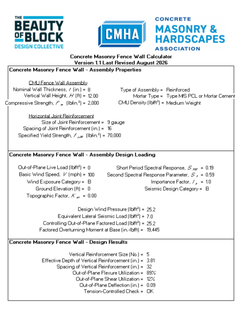
This calculator designs concrete masonry freestanding fence walls in accordance with the strength design provisions of TMS 402/602-22 and the loading criteria of ASCE/SEI 7-22 Chapter 29 for wind loading and Chapter 13 for seismic loading. Loading criteria is based on a uniform loading over wall surface with resultant at mid-height of the assembly. Designs are performed on a normalized per length of wall. Highlighted cells are user inputs. Inputs and outputs use inch-pound units.
User Inputs – Assembly Properties
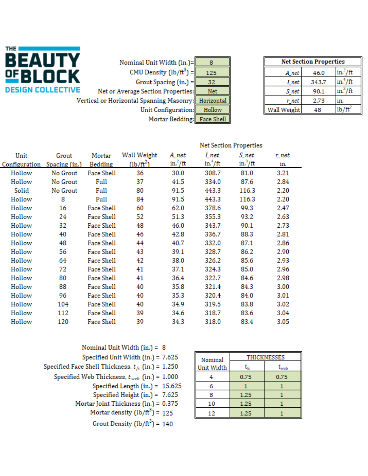
1) Nominal CMU Thickness, t (in.) – Options include 6, 8, 10, and 12 in. concrete masonry units. The specified wall thickness is assumed to be 3/8 in. less than the nominal wall thickness.
2) Vertical Assembly Height (ft) – Fences are assumed cantilevered about the base of the assembly. The wall height is measured from the bottom of the masonry to the top of the assembly.
3) CMU Density (lb/ft3) – Most concrete masonry units have densities that vary from 100 lb/ft3 to 130 lb/ft3, depending on the aggregate used in their production. The density of the CMU is used in determining the assembly weight for applicable out-of-plane design checks, and when applicable, corresponding out-of-plane seismic loads.
4) Masonry Assembly Type – This calculator designs fences as either reinforced or unreinforced based on user selection. For either scenario, the fence assembly is assumed to be a vertically cantilevered element supported solely at the base. Per Section 15.6.8 of ASCE/SEI 7, unreinforced concrete masonry fence wall assemblies are not permitted.
5) Mortar Type – When joint reinforcement is used to resist applied loads, TMS 402 limits the mortar to either portland cement/lime or mortar cement mortars. When the spacing of the vertical reinforcement exceeds 6t (6 times the nominal thickness of the assembly) for reinforced assemblies, this calculator checks the horizontal span between the vertically reinforced sections using joint reinforcement to verify the assembly can safely distribute the applied out-of-plane loads. When these conditions are encountered, the report output notes the mandatory use of joint reinforcement and either portland cement/lime or mortar cement mortar. When designing unreinforced assemblies, or when the spacing of the vertical reinforcement does not exceed 6t, any mortar type may be selected.
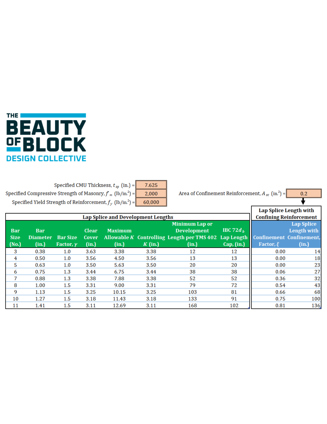
6) Vertical Reinforcement Size (No.) – Vertical reinforcing bar sizes permitted include No. 3 through No. 11 reinforcing bars reflecting the full range of bar sizes permitted by TMS 402.
7) One-Half of Specified Wall Thickness, tsp/2 (in.) – Placing reinforcing bars in the center of the assembly is a common detailing practice. For user convenience, the calculator determines this dimension based on the user-selected nominal wall thickness.
8) Effective Depth of Vertical Reinforcement, d (in.) = Distance from the extreme compression face of the assembly to the center of the vertical reinforcement.
9) Specified Yield Strength of Vertical Reinforcement, fy (lb/in.2) – TMS 402 allows the use of Grade 40, 50, and 60 reinforcing bars, corresponding to specified yield stresses of 40,000 lb/in.2, 50,000 lb/in.2, and 60,000 lb/in.2, respectively.
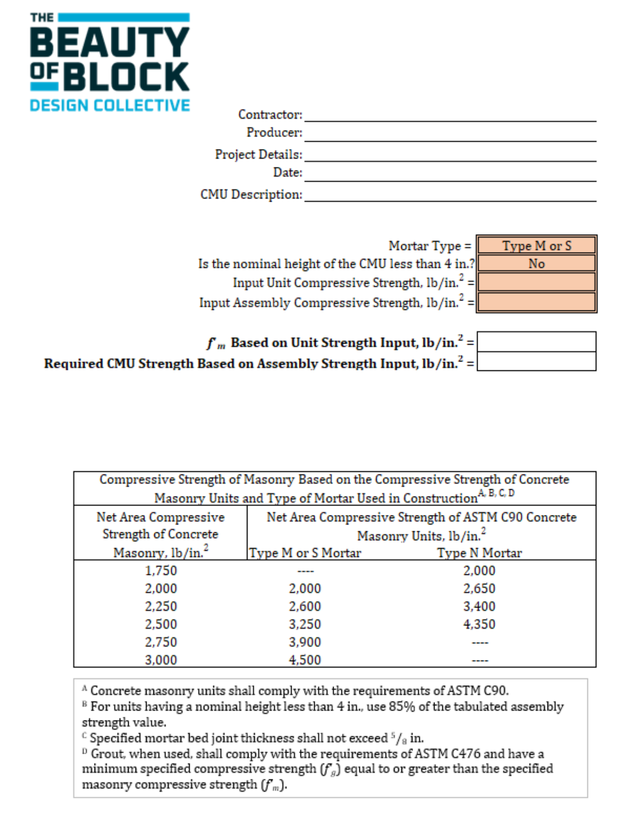
10) Specified Masonry Compressive Strength, f’m (lb/in.2) – A standard concrete masonry unit meeting the minimum requirements of ASTM C90 has a compressive strength of 2,000 lb/in.2. When laid in Type S mortar, the resulting assembly compressive strength (f’m) is 2,000 lb/in.2. When laid in Type N mortar, the resulting assembly compressive strength (f’m) is 1,750 lb/in.2.
11) Size of Joint Reinforcement – The most commonly used/available joint reinforcing size is 9 gauge (W1.7 having a diameter of 0.148 in.) wire, however, TMS 402 allows up to 3/16 in. (W2.8 having a diameter of 0.187 in.) joint reinforcing wire to be used. Specifying 3/16 in. diameter should be done with caution as this is the largest diameter of wire that can be placed in a 3/8 in. thick mortar joint, effectively leaving no room to accommodate construction tolerances or lap splicing of the joint reinforcing.
12) Spacing of Joint Reinforcement (in.) – Joint reinforcement is most commonly spaced at 16 in. on center in concrete masonry construction, but this spacing may be decreased to 8 in. on center where design loads warrant additional horizontal reinforcing steel. Inputs also allow for 4 in. and 12 in. spacing options, but these are only applicable to concrete masonry assemblies constructed using half-high (nominally 4 in. tall) concrete masonry units.
13) Specified Yield Strength of Joint Reinforcement, fyJR (lb/in.2) – Most cold-drawn joint reinforcing wire has a specified yield strength of 70,000 lb/in.2. This is also the maximum specified yield strength permitted by TMS 402 for joint reinforcement.
Tension-Controlled Check
When designing reinforced assemblies, this calculator verifies whether the assembly is tension-controlled per TMS 402. When this design check does not pass, the user is prompted to revise design inputs by reducing the spacing of the vertical reinforcement, increasing the specified masonry compressive strength (f’m), or increasing the wall thickness.
User Inputs – Design Loading
This calculator assumes superimposed axial loads on fences are negligible. Design load inputs consider live, wind, and if applicable, seismic out-of-plane loading.
1)Out-of-Plane Live Loading – Live load design pressures may be added depending on the intended use of the fence wall.
2) Basic Wind Speed, V – The mapped design wind speed for the project location based on the structure’s assigned risk category determined in accordance with ASCE/SEI 7 Chapter 26 and Section 1.5. The basic design wind speed can be determined using the online ASCE Hazard Tool: https://ascehazardtool.org/.
3) Wind Exposure Category – The wind exposure category (B, C, or D) determined in accordance with ASCE/SEI 7 Section 26.7 based on the surface roughness characteristics surrounding the project site.
4) Ground Elevation – Ground elevation above sea level at the project location.
5) Topographic Factor, Kzt – Factor to account for wind speed-up effects due to topography surrounding the project location as determined in accordance with ASCE/SEI 7 Section 26.8.
6) Short Period Spectral Response Parameter, SMS – Determined using the online ASCE Hazard Tool: https://ascehazardtool.org/ for the project location, building risk category, and site soil classification.
7) 1 Second Spectral Response Parameter, S1 – Determined using the online ASCE Hazard Tool: https://ascehazardtool.org/ for the project location, building risk category, and site soil classification. For values of S1 > 0.6, ASCE/SEI 7 requires the seismic response coefficient (Cs) to be calculated using S1.
8) Importance Factor, Ie – Determined in accordance with ASCE/SEI 7 Section 13.1.3. Fence walls that provide a life-safety function to the structure are assigned an importance factor of 1.5.
9) Seismic Design Category – A structure’s seismic classification based on the risk category and severity of the earthquake ground motion. Determined using the online ASCE Hazard Tool: https://ascehazardtool.org/. Per ASCE/SEI 7-22 Section 11.7, nonstructural components and other structures assigned to SDC A are exempt from seismic loading.