User Inputs – Concrete Masonry Screen Wall Design Calculator
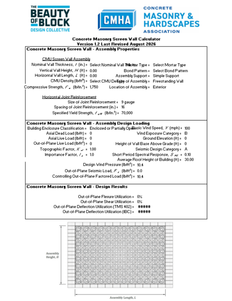
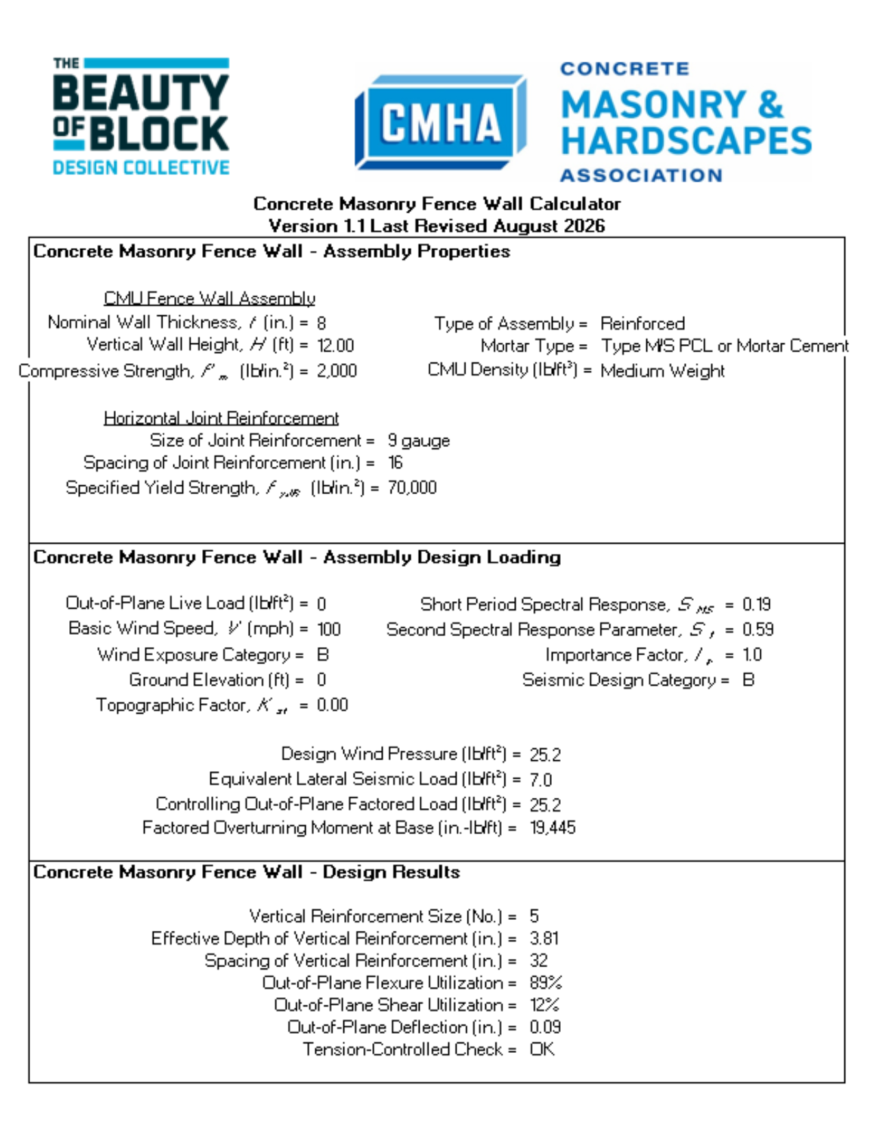
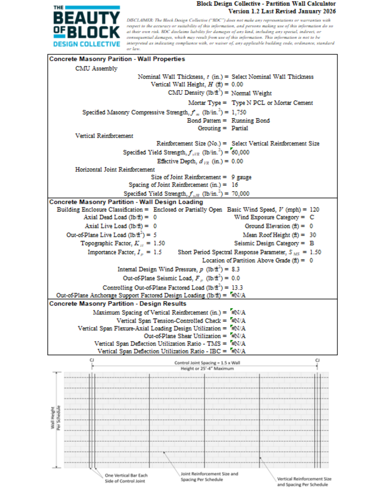
This calculator designs concrete masonry screen walls in accordance with the strength design provisions of TMS 402/602-22 and the loading criteria of ASCE/SEI 7-22 Chapter 28 for interior screen wall assemblies, ASCE/SEI 7 Chapter 29 for exterior screen wall assemblies, and Chapter 13 for seismic loading. Loading criteria is based on a uniform loading over wall surface with resultant at mid-height and mid-length of the assembly. Highlighted cells are user inputs. Inputs and outputs use inch-pound units.
Concrete masonry units used in the construction of open screen walls are available in a wide variety of shapes and configurations. A requisite of this calculator is that the units have full interfacing head and bed joints and are laid in a full bed of mortar at all head and bed joints. Additional information on the detailing and construction of concrete masonry screen wall assemblies is available here: https://www.cmha.org/resource/tek-03-16a/.
User Inputs – Assembly Properties
1) Nominal CMU Thickness, t (in.) – Options include 4, 6, and 8 in. concrete masonry units. The specified wall thickness is assumed to be 3/8 in. less than the nominal wall thickness.
2) Percent Solid of Assembly – The open area of screen block allow wind to pass through the assembly, thereby reducing the design wind pressure. Screen block typically have an open area in the range of 40% to 60%, but could be more or less depending on the configuration of the unit. To be considered an ‘open’ assembly, ASCE/SEI 7 requires a minimum open space of 30%.
3) CMU Density (lb/ft3) – Most concrete masonry units have densities that vary from 100 lb/ft3 to 130 lb/ft3, depending on the aggregate used in their production. The density of the CMU is used in determining the assembly weight for applicable out-of-plane design checks, and when applicable, corresponding out-of-plane seismic loads.
4) Span Direction, Support, and Design Modeling – This calculator allows modeling assuming either vertical or horizontal spanning construction, simple or cantilevered supports, and either reinforced or unreinforced construction. Combinations of these modeling assumptions are limited based on construction practicalities. These include: a) Reinforced assemblies are assumed to span in the horizontal direction only using joint reinforcement given the lack of vertically continuous cells capable of being reinforced. b) A cantilevered assembly is assumed capable of spanning in the vertical direction only.
5) Mortar Type – When joint reinforcement is used to resist applied loads (such as modeled with this calculator when a reinforced assembly is selected), TMS 402 limits the mortar to either portland cement/lime or mortar cement mortars. As such, masonry cement mortar and air-entrained portland cement/lime mortar is not permitted when designing reinforced assemblies using this calculator. Otherwise, any mortar can be used in the construction of screen wall assemblies.
6) Design Span, H or L (ft) – Either the height (vertical) or the length (horizontal) design span length based on user selected span direction. While any design span length may be selected, concrete masonry construction is ideally laid out using modular dimensions that are a multiple of 8 inches.
7) Size of Joint Reinforcement – The most commonly used/available joint reinforcing size is 9 gauge (W1.7 having a diameter of 0.148 in.) wire, however, TMS 402 allows up to 3/16 in. (W2.8 having a diameter of 0.187 in.) joint reinforcing wire to be used. Specifying 3/16 in. diameter should be done with caution as this is the largest diameter of wire that can be placed in a 3/8 in. thick mortar joint, effectively leaving no room to accommodate construction tolerances or lap splicing of the joint reinforcing.
8) Spacing of Joint Reinforcement (in.) – Joint reinforcement is most commonly spaced at 16 in. on center in concrete masonry construction, but this spacing may be decreased to 8 in. on center where design loads warrant additional horizontal reinforcing steel. Inputs also allow for 4 in. and 12 in. spacing options, but these are only applicable to concrete masonry assemblies constructed using half-high (nominally 4 in. tall) concrete masonry units.
9) Specified Yield Strength of Joint Reinforcement, fyJR (lb/in.2) – Most cold-drawn joint reinforcing wire has a specified yield strength of 70,000 lb/in.2. This is also the maximum specified yield strength permitted by TMS 402 for joint reinforcement.
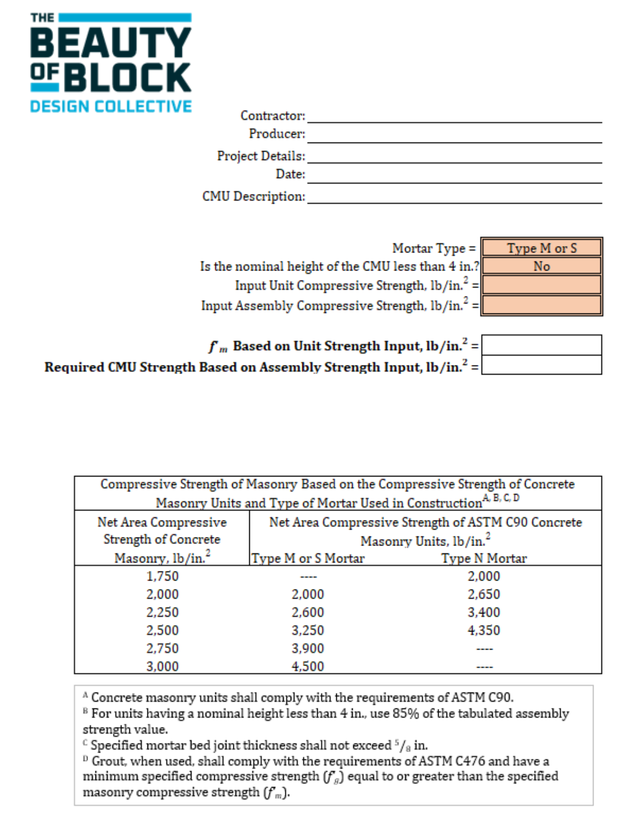
10) Specified Masonry Compressive Strength, f’m (lb/in.2) – In accordance with TMS 402, nonloadbearing walls are permitted to carry only a maximum of 200 lb/ft of allowable stress level axial load in addition to their self-weight. As such, there is usually little structural benefit in specifying a high strength masonry assembly for typical screen wall applications. A standard concrete masonry unit meeting the minimum requirements of ASTM C90 has a compressive strength of 2,000 lb/in.2. When laid in Type S mortar, the resulting assembly compressive strength (f’m) is 2,000 lb/in.2. When laid in Type N mortar, the resulting assembly compressive strength (f’m) is 1,750 lb/in.2.
11) Bond Pattern – Because screen walls designed using this calculator can span in either the horizontal or vertical direction, the selection of the bond pattern affects the modulus of rupture of the assembly, which in turn controls the maximum design span for unreinforced masonry. Note that stack bond construction should not be used with horizontally spanning assemblies as TMS 402 stipulates the modulus of rupture of stack bond construction spanning horizontally is zero.
12) Type of Assembly – Screen walls can be freestanding structures, incorporated into a building envelope, or positioned on a rooftop. The location of the screen wall under these choices changes the design wind pressure reflecting the varying exposure conditions.
13) Location of Assembly – Screen walls designed using this calculator may be located on the interior of a building or exterior, which changes the design wind pressure the assembly is exposed to.
User Inputs – Design Loading
1) Superimposed Axial Loads – TMS 402 permits small axial loads to be applied to nonloadbearing masonry walls, but limits the total allowable stress level axial load to 200 lb/ft or less. Calculator inputs can be either superimposed dead or live loads, provided the combined axial load does not exceed 200 lb/ft. Sign convention is positive (+) for compressive loading and negative (-) for tensile loading. Superimposed loads are assumed to be applied along the top of the wall for design analyses checks.
2) Out-of-Plane Live Loading – ASCE/SEI 7 Section 4.3.4 requires partition walls within buildings that exceed 6 ft in height be designed to resist a horizontal live load of not less than 5 lb/ft2. Other live load design pressures may be more appropriate depending on the intended use of the screen wall.
3) Basic Wind Speed, V – The mapped design wind speed for the project location based on the structure’s assigned risk category determined in accordance with ASCE/SEI 7 Chapter 26 and Section 1.5. The basic design wind speed can be determined using the online ASCE Hazard Tool: https://ascehazardtool.org/.
4) Wind Exposure Category – The wind exposure category (B, C, or D) determined in accordance with ASCE/SEI 7 Section 26.7 based on the surface roughness characteristics surrounding the project site.
5) Ground Elevation – Ground elevation above sea level at the project location.
6) Height of Wall Base Above Grade – The location of the base of the screen wall assembly located above site grade (such as when incorporated as part of a building envelope).
7) Topographic Factor, Kzt – Factor to account for wind speed-up effects due to topography surrounding the project location as determined in accordance with ASCE/SEI 7 Section 26.8.
8) Building Enclosure Classification – Used for determining the internal pressures within a building due to external wind loading as determined in accordance with ASCE/SEI 7 Section 26.12.
9) Short Period Spectral Response Parameter, SMS – Determined using the online ASCE Hazard Tool: https://ascehazardtool.org/ for the project location, building risk category, and site soil classification.
10) Importance Factor, Ip – Determined in accordance with ASCE/SEI 7 Section 13.1.3. Screen walls that provide a life-safety function to the structure are assigned an importance factor of 1.5 as are partitions in buildings assigned to Risk Category IV structures. All other partitions are assigned an importance factor of 1.0.
11) Seismic Design Category – A structure’s seismic classification based on the risk category and severity of the earthquake ground motion. Determined using the online ASCE Hazard Tool: https://ascehazardtool.org/. Per ASCE 7-22 Table 13.3-1, partitions in buildings assigned to SDC A and B are exempt from seismic loading.
12) Average Roof Height of Building – Location of partition within the building above grade used to calculate seismic amplification effects.